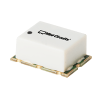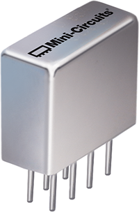

MCDI offers Mini-Circuits RF phase detectors for measuring phase difference between two RF signals in phase-locked loops, phase-monitoring circuits, leveling systems, instrumentation and other RF control applications.
Mini-Circuits phase detectors cover frequencies from 1 MHz to 650 MHz, with surface-mount, coaxial and plug-in configurations.
These high-output phase detectors are designed to provide a DC output related to the phase difference between two same-frequency RF input signals, with low DC offset and high isolation between the RF input ports.
Important selection parameters include:
MCDI’s Application Engineering team in Israel can assist you in selecting the appropriate Mini-Circuits phase detector for your PLL, monitoring, leveling or phase-measurement application.
Hebrew & English Professional Support
Get a quote within hours or less
DDP & Ex-Works - your choice
Custom Adapters & Catalog modifications
Access to Mini-Circuits full portfolio
Mini-Circuits Quality & Reliability
Use the RF Phase Detector Catalog below to search and compare Mini-Circuits models according to your application requirements.
Compare according to:
Compare according to:
Compare according to:
Mini-Circuits also offers a Phase Detector Designer Kit containing multiple detector models for engineering evaluation.
A designer kit can be useful for:
An RF phase detector compares the phase of two RF signals and generates an output voltage related to the phase difference between them.
The two RF signals are normally at the same frequency.
The detector inputs may be identified as:
depending on the device and application.
The resulting DC or low-frequency output provides information about the relative phase between the two inputs.
This makes phase detectors useful for:
Measurement systems
Mini-Circuits phase detectors use a balanced mixer-type architecture.
When two RF signals at the same frequency are applied to the detector, the output contains a component related to the phase difference between them.
After the unwanted high-frequency components are removed, the remaining DC voltage can be used as an error signal.
The output changes as the relative phase between the two RF inputs changes.
At one phase relationship the output reaches a positive or negative maximum, while at the opposite phase relationship it reaches the opposite polarity.
Near the appropriate quadrature operating point, the phase-to-voltage relationship is approximately linear.
This linear region is particularly useful in closed-loop systems such as PLLs.
One of the principal applications for an RF phase detector is a phase-locked loop – PLL.
A basic PLL may contain:
Reference Signal → Phase Detector → Loop Filter → VCO → Feedback Path
The phase detector compares:
If their phases differ, the detector generates an error voltage.
The loop filter processes this error signal and applies the resulting control voltage to the VCO.
The PLL continuously adjusts the oscillator until the feedback signal maintains the required phase relationship with the reference.
The Mini-Circuits products on this page are analog RF phase detectors.
They directly compare RF signals and produce an analog DC output related to phase difference.
This is different from the digital phase-frequency detector – PFD architecture commonly integrated into modern PLL synthesizer ICs.
Typically used when:
Typically used inside:
The appropriate approach depends on the complete PLL or measurement architecture.
Mini-Circuits offers compact surface-mount high-output phase detectors for PCB-level integration.
Current models include frequency coverage such as:
depending on model.
Surface-mount phase detectors are suitable for:
Benefits include:
Connectorized phase detectors are convenient for laboratory, test and system-level applications.
They can be placed directly into a coaxial RF setup without PCB integration.
Applications include:
Mini-Circuits’ ZRPD-series provides rugged connectorized phase-detector solutions.
Mini-Circuits also offers plug-in phase detectors for through-hole PCB integration and legacy RF designs.
These products are useful for:
Models include MPD- and RPD-series high-output phase detectors.
One of the most important specifications is the scale factor, normally expressed in:
mV / degree
The scale factor indicates how much the phase-detector output voltage changes for a given change in phase within its approximately linear operating region.
For example:
8 mV/degree
means that a 1° change in phase produces approximately an 8 mV change in output voltage under the specified test conditions.
A higher scale factor produces a larger error-voltage change for a given phase difference.
This can be useful in:
In a PLL, the phase detector’s scale factor becomes part of the loop gain.
A higher detector gain means a small phase error produces a larger control signal.
The complete loop response also depends on:
The phase detector should therefore be selected together with the VCO and loop-filter architecture rather than as an isolated component.
Mini-Circuits high-output phase detectors provide a relatively large DC output as phase changes.
Selected models provide typical maximum DC output levels around 900 to 1000 mV under their specified RF input conditions.
A larger available detector output can simplify the design of the following loop-filter or control circuitry.
Always verify:
using the individual datasheet.
DC offset is the residual output voltage present when the detector would ideally produce zero output.
Offset can arise from:
Low DC offset is important because an offset voltage can be interpreted by the control system as a phase error.
Mini-Circuits phase detectors are optimized for low DC offset, with selected models specified at typical levels below 1 mV.
For precision applications, include DC offset in the system phase-error budget.
RF1-RF2 isolation indicates how well the two RF input ports are isolated from one another.
High isolation helps prevent one RF signal from leaking directly into the other signal path.
This can be important in:
Selected Mini-Circuits phase detectors provide minimum RF1-to-RF2 isolation of 40 dB, while performance depends on model and frequency.
Phase-detector performance depends on the RF level applied to both RF inputs.
The current Mini-Circuits high-output phase-detector catalog specifies key performance parameters using approximately:
+7 dBm per RF input
for the principal models.
This value should be treated as the specified test / operating input level for the published phase-detector performance, not automatically as the device’s absolute maximum input rating.
Always check the individual datasheet for:
The phase detector’s DC output is designed to operate with a defined load impedance.
Current high-output Mini-Circuits phase detectors typically specify:
500 Ω DC output impedance
for the principal catalog models.
The following loop-filter or measurement circuit should be designed so that loading does not significantly alter detector behavior.
The phase detector output can be positive or negative depending on:
Mini-Circuits therefore specifies the output polarity with the RF inputs in phase.
For several current products the output polarity is specified as negative when RF1 and RF2 are in phase.
This specification becomes important when determining the feedback polarity of a PLL.
If the feedback sign is incorrect, the loop may move away from lock rather than toward it.
Mini-Circuits specifies a phase-detector Figure of Merit – M as an efficiency indicator for its high-output detector family.
It relates the maximum available DC output to the RF input level used to drive the detector.
Higher M indicates that the detector generates a relatively large DC output for the applied RF drive.
Current Mini-Circuits products include typical values such as:
depending on model.
Figure of Merit is useful for comparing Mini-Circuits high-output phase-detector models, but system selection should still consider frequency range, scale factor, isolation, offset and output loading.
Both RF inputs must be within the detector’s specified operating-frequency range.
Mini-Circuits’ current dedicated phase-detector portfolio spans 1 to 650 MHz.
Available ranges include products optimized for:
depending on model.
Make sure both RF signals can provide the required detector drive.
If the available signals are too weak, RF amplification may be necessary before the detector.
Select the required phase-to-voltage sensitivity.
Higher mV/degree can provide more loop or measurement sensitivity, but the complete control-system gain should be considered.
For precision phase control, low DC offset helps minimize static phase error.
High isolation may be important where coupling between the reference and measured signal could disturb the sources.
Confirm that the detector output is sufficient for:
without requiring excessive additional amplification.
For PLL applications, confirm that the phase-detector polarity produces the correct negative-feedback direction when combined with the VCO tuning characteristic.
Choose:
Surface Mount
for compact PCB-level integration.
Coaxial
for laboratory and system-level use.
Plug-In
for through-hole integration and existing designs.
A double-balanced mixer – DBM and an RF phase detector can use very similar internal circuitry.
A mixer can act as a phase detector when:
Under these conditions, the DC output depends on the relative phase between the RF and LO signals.
Dedicated Mini-Circuits phase-detector models are characterized specifically for phase-detection parameters such as:
This makes system design easier when these phase-detection specifications are important.
Mini-Circuits offers a much broader mixer portfolio over much higher frequencies.
A mixer with an IF response extending to DC can therefore be useful when a dedicated phase-detector product does not cover the required carrier frequency.
Always evaluate the mixer specifically under phase-detector operating conditions.
Mini-Circuits’ dedicated high-output phase-detector family extends to 650 MHz.
For phase-detection applications above this frequency, selected double-balanced mixers with IF response extending to DC may also be suitable.
This can significantly extend the available RF frequency range.
Mixer selection for phase detection should consider:
MCDI’s Application Engineers can help identify an appropriate dedicated phase detector or mixer-based solution.
In addition to PLLs, phase detectors can be used in RF monitoring and control systems.
Applications can include:
The DC detector output can be read by:
to monitor or control relative signal phase.
Phase detectors generate the phase-error signal required to control a VCO and maintain frequency / phase lock.
Analog phase detectors can form part of frequency-generation systems where a tunable oscillator is locked to a stable reference.
A phase detector can compare a VCO-derived feedback signal with a reference and generate the error voltage used to tune the oscillator.
The detector output can be monitored to measure changes in relative phase between two same-frequency RF signals.
Phase-detector outputs can be incorporated into analog feedback and control systems.
Connectorized phase detectors are convenient for:
A phase detector can be used to determine phase error between a reference signal and a synchronized oscillator or RF source.
A phase detector is often used together with components that actively control phase or frequency.
For example:
Reference → Phase Detector → Control Circuit → Phase Shifter
can create a closed-loop phase-control system.
Similarly:
Reference → Phase Detector → Loop Filter → VCO
creates the basis of an analog PLL.
MCDI can assist with Mini-Circuits:
for complete RF phase-control architectures.
An RF phase detector compares two RF signals at the same frequency and generates a DC or low-frequency output related to their phase difference.
Mini-Circuits’ current dedicated high-output RF phase-detector portfolio covers frequencies from 1 MHz to 650 MHz, depending on model.
Scale factor describes how much the detector output voltage changes for a given change in phase.
It is typically expressed in mV per degree.
A scale factor of 8 mV/degree means that, within the specified approximately linear region, a 1° change in phase produces approximately an 8 mV change in detector output.
DC offset is the residual output voltage present when the ideal phase-detector output should be zero.
Lower offset helps reduce phase-measurement or control-loop error.
High isolation reduces direct signal leakage between the two RF inputs.
This helps prevent the reference and measured signals from disturbing one another.
Output polarity indicates whether the detector produces positive or negative DC voltage for a specified relative phase relationship between its RF inputs.
It is important when determining the feedback direction in a PLL.
Figure of Merit M is a Mini-Circuits metric used to describe phase-detector efficiency based on DC output relative to the RF input level.
Higher values indicate larger available DC output for the specified RF drive.
Yes.
PLLs are one of the main applications for RF phase detectors.
The detector produces a phase-error signal used by the loop filter to control the VCO.
The current high-output Mini-Circuits models are principally characterized using approximately +7 dBm at each RF input.
Always check the individual datasheet for the correct operating conditions and absolute maximum rating.
No.
The RF input level used to specify phase-detector performance should not automatically be interpreted as the device’s maximum safe input rating.
Always check the maximum-rating section of the individual datasheet.
Yes.
A double-balanced mixer can operate as a phase detector when the RF and LO signals are at the same frequency and the IF response extends to DC.
Mini-Circuits’ mixer portfolio therefore provides additional options for phase detection, especially at frequencies above the dedicated phase-detector range.
Dedicated phase detectors are characterized specifically for phase-detection parameters such as scale factor, DC output, offset, isolation, polarity and Figure of Merit.
This makes design and component selection easier when these parameters are important.
Yes.
Although Mini-Circuits’ dedicated phase-detector family extends to 650 MHz, selected double-balanced mixers with IF response to DC can potentially be used as phase detectors at much higher frequencies.
The mixer must be evaluated for the specific application.
A phase detector measures or compares phase difference.
A phase shifter changes the phase of an RF signal.
The two components may be used together in a closed-loop phase-control system.
Yes.
MCDI’s Application Engineering team in Israel can help identify a suitable Mini-Circuits phase detector according to frequency, RF drive level, scale factor, output, offset, isolation and PLL requirements.
MCDI is Mini-Circuits’ exclusive representative and distributor in Israel, providing Israeli engineers and purchasing teams with access to Mini-Circuits RF products together with local technical, commercial and logistical support.
Local Application Engineering
Phase-detector selection requires consideration of:
MCDI’s Application Engineers can help evaluate these requirements and identify the appropriate Mini-Circuits phase detector or mixer-based alternative.
Technical Support in Hebrew and English
Discuss your PLL, phase-control or measurement requirements directly with an Israel-based engineering team familiar with Mini-Circuits RF components.
Complete PLL & Phase-Control Support
MCDI can assist with related Mini-Circuits products including:
allowing the phase detector to be evaluated within the complete control-loop architecture.
Support from Selection Through Delivery
MCDI supports customers in Israel from product selection and quotation through ordering, logistics and post-sales technical assistance.




Before you leave, you should know that MCDI’s professional team of Application Engineers will be delighted to assist you in sourcing the right component. Just fill the form and we will be back to you shortly.