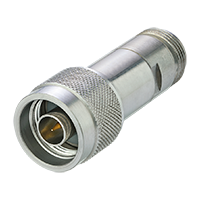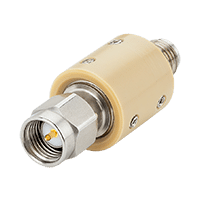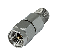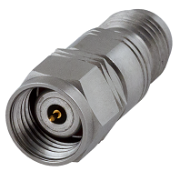

MCDI offers a selection of Mini-Circuits RF, microwave and millimeter-wave DC blocks designed to prevent unwanted DC voltage or current from passing through an RF signal path while maintaining low-loss transmission of the RF signal.
The portfolio includes wideband coaxial DC blocks for 50 Ω and selected 75 Ω systems, with connector interfaces including SMA, N-Type, BNC, 2.92 mm, 2.4 mm and 1.85 mm.
Mini-Circuits DC blocks cover RF frequencies from 100 kHz to 65 GHz, with models optimized for low insertion loss, good impedance matching and rugged laboratory or system use.
DC blocks are commonly used to protect RF test equipment, isolate DC bias between stages and prevent unwanted DC from reaching sensitive RF components.
MCDI’s Application Engineering team in Israel can assist you in selecting the correct DC block according to frequency range, insertion loss, return loss, impedance, DC voltage requirements, connector type and whether DC isolation is required on the inner conductor only or on both inner and outer conductors.
Hebrew & English Professional Support
Get a quote within hours or less
DDP & Ex-Works - your choice
Custom Adapters & Catalog modifications
Access to Mini-Circuits full portfolio
Mini-Circuits Quality & Reliability
Use the RF DC Block Catalog below to search and compare available Mini-Circuits models according to your application requirements.
Search and filter according to:
For complete electrical, mechanical, environmental, voltage and RF power specifications, always review the individual Mini-Circuits product datasheet.
An RF DC block is a passive component designed to allow RF or microwave signals to pass while preventing DC current from flowing through part of the signal path.
In its simplest form, a DC block uses capacitive coupling. The capacitor prevents steady-state DC current from passing while allowing sufficiently high-frequency RF signals to propagate.
This makes a DC block useful whenever an RF signal needs to pass between two devices that operate at different DC bias conditions or where sensitive equipment needs protection from unwanted DC voltage.
Typical uses include:
Not all DC blocks isolate the same conductors. Understanding the internal configuration is particularly important when the coaxial outer conductor may also carry unwanted DC current.
Inner-Conductor DC Blocks
An inner DC block blocks the DC path through the center conductor of the coaxial connection while maintaining DC continuity through the outer conductor or shield.
This is the most common DC-block configuration.
It can be used where:
Mini-Circuits offers inner DC blocks across multiple connector families and frequency ranges.
Inner-Outer DC Blocks
An inner-outer DC block provides DC isolation on both the center conductor and the outer conductor.
This configuration may be useful where complete DC isolation between the two sides of the coaxial connection is required.
Applications can include:
Mini-Circuits’ BLKD-series includes inner-outer DC-block configurations.
Always review the electrical schematic in the individual product datasheet to confirm exactly which conductors are DC isolated.
Selecting the correct DC block requires more than simply matching the RF connectors.
The minimum operating frequency is especially important in a DC block because the internal capacitive element behaves differently as frequency decreases.
At lower frequencies, capacitive reactance increases. If a DC block is used below its specified operating range, insertion loss and impedance matching may degrade.
Mini-Circuits models are available with minimum RF frequencies as low as 100 kHz, depending on the product.
Always choose a model whose specified lower-frequency limit is below the lowest RF frequency required by your system.
The DC block must also maintain suitable insertion loss and return loss through the highest operating frequency of the application.
Mini-Circuits’ current coaxial DC-block portfolio extends to 65 GHz.
Precision high-frequency connector interfaces used across the range include:
Always verify the complete product specification rather than assuming that connector capability alone determines the DC block’s usable frequency.
Insertion loss describes the RF signal loss introduced when the DC block is inserted into the signal path.
Lower insertion loss is generally desirable, particularly in:
Review insertion loss across the entire required frequency range.
A DC block becomes part of the RF transmission line and therefore affects impedance matching.
Good return loss or low VSWR helps minimize reflections between the DC block and adjacent RF components.
This is particularly important in:
Check return loss across the actual operating band rather than relying on a single-frequency value.
The DC block must safely withstand the DC voltage that may appear across the isolated conductor or conductors.
The maximum permitted DC voltage varies by model.
Never assume that two DC blocks with the same frequency range or connector type have the same voltage capability.
Always verify the individual datasheet when significant DC voltage is present.
The RF signal itself also contributes power to the component.
For applications involving higher RF power, review the specified RF power handling and any frequency or environmental derating requirements.
Most RF and microwave applications use 50 Ω systems.
Mini-Circuits also offers selected 75 Ω DC blocks for applications such as broadband and CATV systems.
The DC block impedance should match the RF system.
Choose a connector suitable for both the existing equipment and the required operating frequency.
Current Mini-Circuits DC-block options include:
High-frequency applications typically require precision microwave connector interfaces.
Connectorized DC blocks may use combinations such as female-to-male.
Choosing a configuration that mates directly with the equipment can eliminate unnecessary RF adapters and additional connection points.
This can reduce:
Determine exactly where unwanted DC may exist.
Choose an inner DC block when only the center conductor requires DC isolation.
Choose an inner-outer DC block when both the center and outer conductor need to be isolated from DC continuity.
Always check the individual product schematic before final selection.
RF DC blocks are used throughout test systems, communications equipment and RF signal chains where DC isolation is required without interrupting the RF signal.
One of the most common uses of a DC block is protecting sensitive test equipment from unexpected DC voltage.
Equipment such as:
may have limits on the amount of DC voltage permitted at their RF inputs.
A correctly selected DC block can provide an additional layer of protection by preventing DC on the device-under-test side from reaching the instrument.
Always observe the instrument manufacturer’s own maximum input specifications.
DC blocks are frequently used in VNA setups when measuring active or biased RF devices.
They allow the RF test signal to pass while isolating the VNA from DC bias applied to the device under test.
This can be useful when characterizing:
Many amplifiers operate with internal or external DC bias.
A DC block can isolate unwanted DC between the amplifier and other RF equipment while allowing the RF signal to continue through the test setup.
Two RF stages may need to exchange an RF signal while operating at different DC potentials.
A DC block allows RF coupling between those stages while preventing direct DC current flow through the isolated conductor.
DC blocks can be useful throughout transmitter and receiver signal chains where unwanted DC offsets must be prevented from reaching adjacent RF components.
High-frequency DC blocks using 2.92 mm, 2.4 mm and 1.85 mm connectors allow DC isolation to be maintained in microwave and mmWave test setups.
Selected Mini-Circuits models support applications through 65 GHz.
Most DC blocks are used in conventional 50 Ω RF systems, while selected 75 Ω models support broadband and CATV applications.
Always maintain consistent impedance throughout the signal chain.
A DC block and a bias tee perform related but fundamentally different functions.
A DC block:
A bias tee:
For example, if an RF amplifier needs DC power delivered through its RF connection, a bias tee may be used to add the DC.
If the test instrument connected farther along the RF line must be protected from that DC voltage, a DC block may be used to prevent the DC from reaching the instrument.
DC blocks are particularly useful RF accessories for laboratories because they can be added directly into coaxial test setups without redesigning the device under test.
A typical RF test bench may combine a DC block with:
Selecting compatible impedance, frequency range and connector interfaces across all these components helps maintain measurement quality.
An RF DC block is a passive component that allows RF or microwave signals to pass while preventing direct current from flowing through the isolated part of the coaxial signal path.
A conventional inner-conductor DC block uses capacitive coupling.
A capacitor interrupts the DC current path while presenting sufficiently low reactance to RF signals within the specified operating-frequency range.
A DC block may be used to:
An inner DC block prevents DC current from passing through the coaxial center conductor while maintaining continuity through the outer conductor.
An inner-outer DC block prevents DC continuity through both the center conductor and outer conductor.
It can be useful when DC isolation is required on both parts of the coaxial connection.
A DC block prevents DC from passing along the RF signal path.
A bias tee intentionally combines or separates RF and DC using a dedicated DC port.
A system may use both components when DC needs to be injected at one point and blocked before reaching another device.
A correctly selected DC block can prevent DC voltage on the device-under-test side from reaching the VNA RF port.
However, the DC block and VNA specifications must both be observed, and the DC block should not be treated as a substitute for following the instrument manufacturer’s input limits and safety instructions.
The capacitor used to block DC has frequency-dependent reactance.
As frequency decreases, its reactance increases, which can increase insertion loss and degrade matching.
This is why DC blocks have a specified minimum RF operating frequency.
Insertion loss is the RF signal loss introduced by placing the DC block in the transmission path.
Lower insertion loss is generally preferred, particularly in sensitive or precision RF systems.
Return loss indicates how well the DC block is impedance matched to the system.
Better return loss means less RF energy is reflected back toward the source.
Mini-Circuits currently offers coaxial DC-block models covering RF frequencies from approximately 100 kHz to 65 GHz, depending on the individual model.
Current Mini-Circuits DC blocks include models with SMA, N-Type, BNC, 2.92 mm, 2.4 mm and 1.85 mm interfaces.
Yes. Mini-Circuits offers selected 75 Ω DC-block models in addition to the broader 50 Ω range.
DC voltage capability varies by product.
Selected models support substantial DC voltage, but the exact absolute maximum rating must always be verified in the individual product datasheet.
Yes. MCDI’s Application Engineering team in Israel can help identify appropriate Mini-Circuits DC blocks according to frequency, insertion loss, return loss, impedance, DC voltage, connector and isolation requirements.
MCDI is Mini-Circuits’ exclusive representative and distributor in Israel, providing Israeli engineers and purchasing teams with access to Mini-Circuits RF, microwave and millimeter-wave products together with local technical, commercial and logistical support.
Local Application Engineering
Selecting a DC block may require balancing minimum and maximum RF frequency, insertion loss, return loss, DC voltage, connector type and isolation architecture.
MCDI’s Application Engineers can help evaluate these requirements and identify suitable Mini-Circuits models.
Technical Support in Hebrew and English
Discuss your application directly with an Israel-based engineering team familiar with Mini-Circuits RF components and systems.
Test Setup Assistance
If your application combines DC bias and RF measurement, MCDI can help identify the appropriate combination of DC blocks, bias tees, cables, adapters and other RF accessories.
Product Selection Assistance
If you know the frequency range and connector type but are unsure which DC block to use, send MCDI your application requirements for evaluation.
Support from Selection Through Delivery
MCDI supports customers in Israel from product selection and quotation through ordering, logistics and post-sales technical assistance.




Before you leave, you should know that MCDI’s professional team of Application Engineers will be delighted to assist you in sourcing the right component. Just fill the form and we will be back to you shortly.