Reflectionless Filter Basics: A Brief History of the Genesis of Reflectionless Filters
Introduction
The advent of broad bandwidth amplifiers, analog-to-digital converters (ADCs), digital-to-analog converters (DACs), and software-defined radios has brought about growing interest in broadband communications, radar, and sensing applications. For these applications, there is often a need to preserve the highest sensitivity and dynamic range possible within the receiver signal chain and to mitigate the number and strength of harmonics and spurious content in the transmitter signal chain. This is a substantial challenge considering the nature of non-linear components within these circuits, namely compression-mode amplifiers, mixers, multipliers, and frequency-conversion electronics.
A long-overlooked opportunity to enhance the signal-to-noise ratio (SNR) and dynamic range within a signal chain and to reduce harmonics/spurious content within these circuits is to address a seemingly innate property of filters: their out-of-band reflective behavior. Reflectionless filters utilize a novel circuit topology to effectively eliminate the standing waves created by traditional filters without additional components (such as pads). This unique property gives designers a new way to improve the system performance of a wide array of broadband circuits, or any circuits suffering from out-of-band impedance mismatch.
Reflectionless filters were born from a desire to enhance the signal chain performance of sensitive radio astronomy receivers. Innovators of the technology noted that the typical performance of conventional filters (reflective filters) only exhibited a matched impedance at its ports within the filter’s pass-band. The stop-band regions of these filters are intentionally designed to have very poor impedance match. As a result, undesired stop-band signals, including harmonics, interference, and noise, are all reflected from the filter ports back through the signal chain. If these unwanted signals are reflected back to another reflective device, a standing wave effect emerges. This standing wave will persist and build on itself until the attenuation of the transmission path between the two reflective components dampens and absorbs the unwanted signal energy.
In the case of non-linear devices (amplifiers, mixers, converters, etc.), this standing wave can lead to a number of undesirable effects including:
- Gain compression
- Oscillations
- Proliferation of spurious mixing products
- Unexpected resonances
- Degraded stability
- Degraded dynamic range
- Greater susceptibility to process tolerances/environmental factors
- Biasing issues
Hence, it is often necessary to insert isolators or attenuators (pads) into the signal path to dampen this standing wave effect. However, neither isolators nor pads are an ideal solution for most applications. Isolators are band-limited devices with a large footprint, while attenuators are broadband absorbers that absorb even pass-band signal energy. The increased insertion loss from either of these methods may lead to the need for additional gain in the system, and both solutions add cost, size, complexity, and failure points to the circuit.
A better solution is to design a filter that absorbs signal energy in the stop-band instead of reflecting it. Though absorptive filter technologies have existed for some time, their design and implementation didn’t meet all of the desired criteria for a true conventional filter replacement. Hence, a ground-up design effort culminated in the birth of the reflectionless filter, which is a set of filter topologies and designs that inherently exhibit a broadband matched impedance.
Overview of Reflectionless Filter Theory
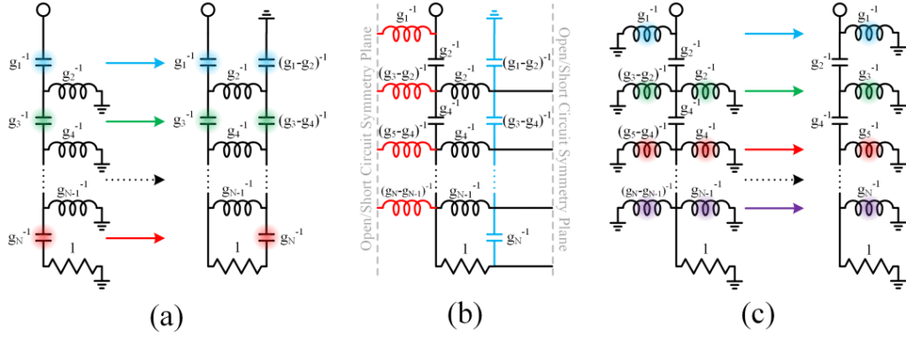
Reflectionless filter topologies are often realized as symmetric networks. This enables the use of even-/odd-mode analysis techniques, which aids in understanding the reflectionless nature of these filters. Given a two-port network with a perfect symmetry plane dividing the circuit, there are two modes useful for analysis. The even mode occurs when both ports are stimulated by signals of equal amplitude and phase, which means there is no current passing across the symmetry plane. The odd mode occurs when the signals stimulated at either port are equal in amplitude and opposite in phase (180 degrees out of phase), and where the voltage potential at the nodes along the symmetry plane is 0 referenced to ground.
Under these conditions, two separate single-port networks can be drawn, each with only half the elements of the original two-port network with the nodes along the symmetry plane either shorted to ground or open (odd-mode circuits and even-mode circuits). Hence, the scattering parameters of the two-port network can be derived from the superposition of the reflection coefficients of the two circuits detailed in Equations 1 and 2.
Equation 1:

Equation 2:

Given the S-parameters, a condition of exact input match (S11 = S22 = 0) can be derived from Equation 3. This condition can only be satisfied if the even-mode and odd-mode circuits are duals of each other (i.e. where their reflection coefficients are additive inverses of one another), which means that the inductors and capacitors, along with the series and shunt elements within each circuit are swapped compared to the other. The result of the combined circuit is a transfer function for the original two-port network equivalent to the reflection coefficient of the even-mode circuit.
Equation 3:

Therefore, low-pass, high-pass, band-pass, and band-stop filters can be generated by choosing a filter topology whose reflection characteristic matches the desired transfer characteristic (even-mode circuit), creating a dual of the chosen filter topology (odd-mode circuit), performing topological modifications that result in symmetry between the even-/odd-mode circuits without affecting the circuit behavior, then combining the two circuit-halves to form the final two-port filter network (See Figures 1 and 2).
It is important to note that for some filter responses, such as Chebyshev, the filter ripple is bounded by the need to maintain positive element values (unless a modification is applied which requires the use of transformers [6]). Hence, for these types of filters there is an additional limit to the stop-band rejection, which means the stop-band rejection only reaches approximately 13-14 dB and is somewhat dependant on the order of the filter. Therefore, when using these filter types to design reflectionless filters it may be necessary to cascade several filters or use a filter response less encumbered by this restriction (i.e. Zolotarev response).


A Note on Practical Reflectionless Filters
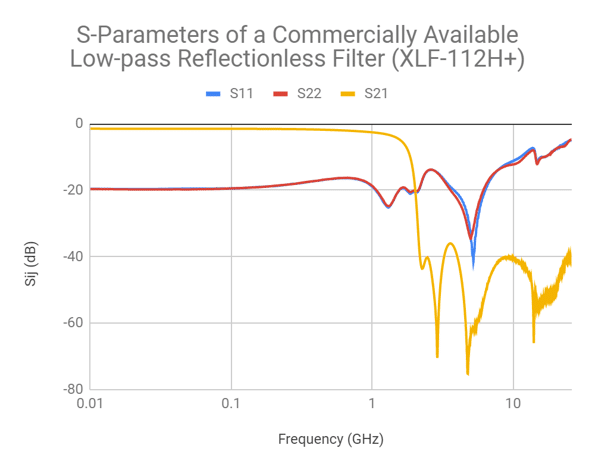
In their current incarnation, reflectionless filters have been mass-produced using a gallium arsenide (GaAs) semiconductor Integrated Passive Device (IPD) fabrication process (see Figure 4). Reflectionless filters with frequency response from hundreds of megahertz to over 30 gigahertz have been realized [9, 10}. A benefit of the GaAs IPD process is that the resulting reflectionless filters are also extremely stable over temperature and exhibit a relatively high operating temperature beyond 100 degrees C.

As with any practical filter, additional loss and parasitics do affect performance relative to the ideal filter circuit. In the case of the GaAs IPD process, the extremely small filters are built with equally compact and planar spiral inductors and capacitors, which have relatively low Q values. Hence, the tradeoff for extremely compact size (3×3 QFN package) and excellent repeatability in these filters is generally greater characteristic insertion loss. However, a benefit of the reflectionless filter topology is that these filters are readily cascadable, so sharper roll-off and greater stop-band rejection may be achieved by adding filters as modular building blocks.
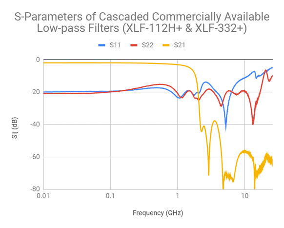
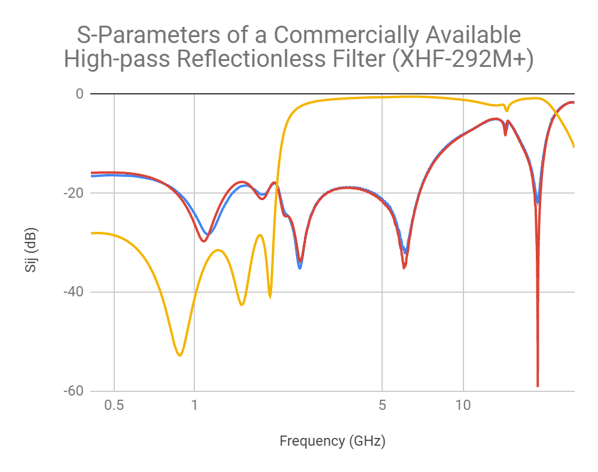
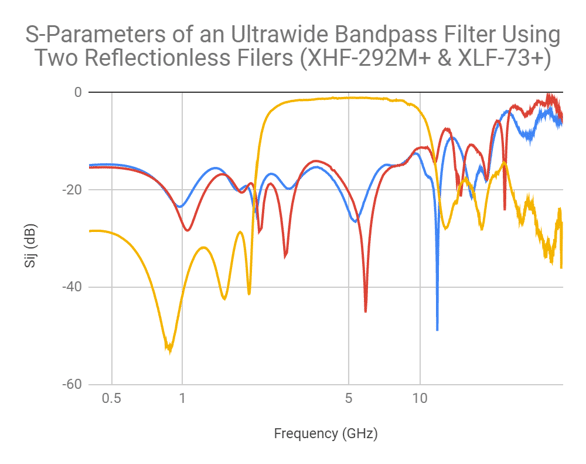
This cascadability allows designers to combine reflectionless filters to achieve a desired response. For example, reflectionless filters may be cascaded to enhance a filter’s stop-band attenuation, extend the stop-band match, or create ultra-wideband (UWB) filters. The examples plotted in Figure 5 show that the stop-band attenuation, which is ultimately limited by the fabrication constraints of the GaAs IPD process, can be improved by combining two complementary low-pass reflectionless filters. Moreover, Figure 6 illustrates that a UWB band-pass filter with good stop-band match can be achieved by combining a low-pass and a high-pass reflectionless filter.
Reflectionless Filters versus Conventional Filters
It is easy enough to understand the value of having pass-band and stop-band matched impedance at each port of a filter in concept, but it is more instructive to see practical results of the difference between reflective and reflectionless filters in specific implementations. The following examples and discussion revolve around the effects of cascading both reflective and reflectionless filters. Here we examine the negative performance impacts of poor impedance match, compared to filters that are matched at every frequency.
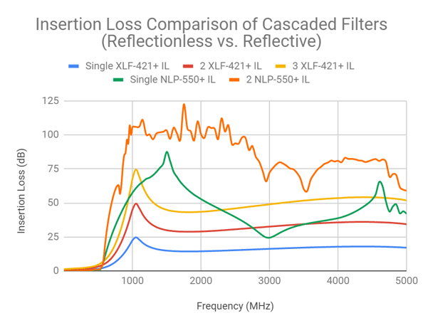
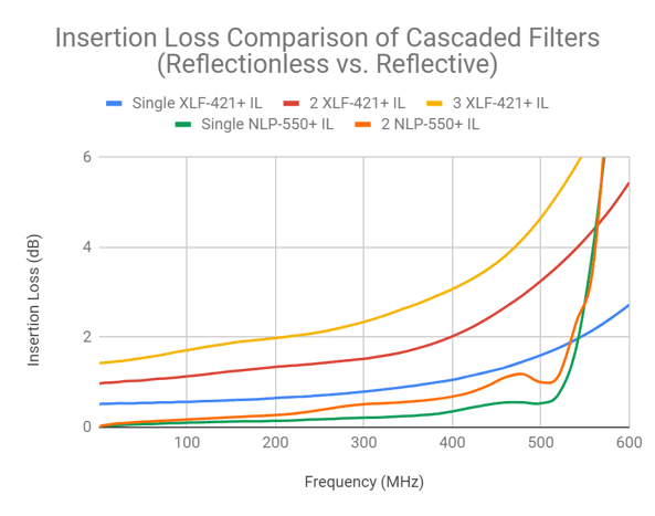
Whereas cascading conventional filters can lead to ripple and cause phase instability in the pass-band, these same concerns are not applicable to reflectionless filters. For example, when comparing conventional filters with reflectionless filters in series, the cascaded conventional filter response will likely suffer from increased ripple in the stop-band due to an unstable phase relationship between the through and reflected signal. Moreover, a conventional filter will also suffer from additional pass-band ripple as a product of the resulting reflections in the transition. Cascading reflectionless filters, by contrast, eliminates the distortion and additional ripples common to conventional filters, but creates an expected accumulation of insertion loss (see Figure 7) [10].
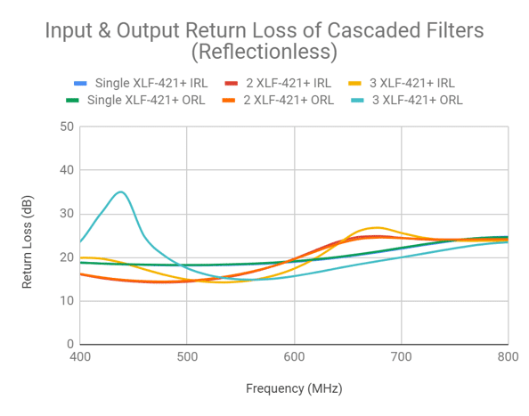
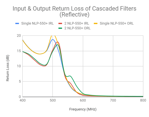
When cascaded, conventional reflective filters also suffer degradation of input and output return loss of the transition corner response due to their poor match in the transition. For example, Figure 8 compares the input and output return loss of cascaded reflective and reflectionless filters. The input and output return loss of just two conventional filter sections in cascade varies significantly around the cutoff frequency. By contrast, the three-section cascaded reflectionless filter exhibits relatively consistent input and output return loss in the pass-band to stop-band transition. This example indicates that where cascading conventional filters degrades the filter’s frequency response (i.e. passband performance), cascading reflectionless filters simply adds a predictable amount of insertion loss without other unwanted effects.
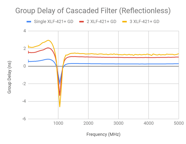
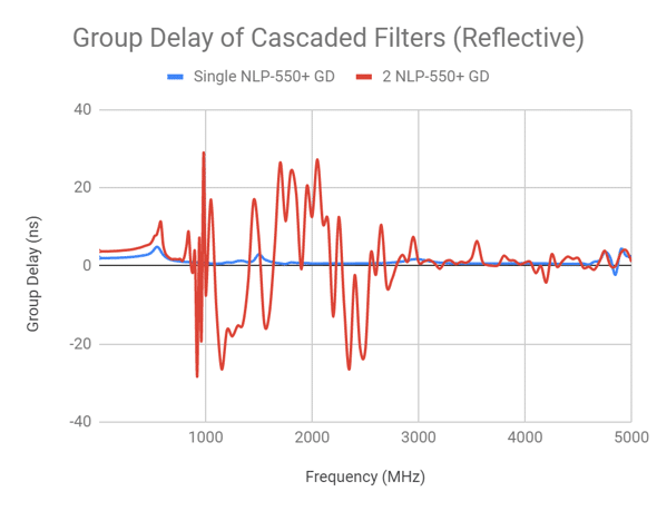
Lastly, the reactive impedance of a conventional filter tends to result in distortion and phase instability, which worsens as filter sections are added. These performance degradations directly impact the group delay performance of conventional cascaded filters (see Figure 9) [10]. Cascaded reflectionless filters, on the other hand, exhibit relatively flat group delay through the pass-band, transition, and stop-band.
References
- M. Morgan, “A better way to filter — part I,” NRAO Blog, March 29, 2018.
- M. Morgan, Reflectionless Filters, Norwood, MA: Artech House, January 2017.
- Hong J, (ed.). Advances in Planar Filters Design. Institution of Engineering and Technology, 2019. 424 p.
- Morgan, M. A., & Boyd, T. A. (2011). Theoretical and Experimental Study of a New Class of Reflectionless Filter. IEEE Transactions on Microwave Theory and Techniques, 59(5), 1214–1221. doi:10.1109/tmtt.2011.2113189
- Morgan, M. A., & Boyd, T. A. (2015). Reflectionless Filter Structures. IEEE Transactions on Microwave Theory and Techniques, 63(4), 1263–1271. doi:10.1109/tmtt.2015.2403841
- Morgan, M. A., Groves, W. M., & Boyd, T. A. (2018). Reflectionless Filter Topologies Supporting Arbitrary Low-Pass Ladder Prototypes. IEEE Transactions on Circuits and Systems I: Regular Papers, 1–11. doi:10.1109/tcsi.2018.2872424
- M. Morgan, “Think Outside the Band: Design and Miniaturization of Absorptive Filters,” IEEE Microwave Magazine, vol. 19, no. 7, pp. 54-62, November 2018.
- R. Setty, B. Kaplan, M. Morgan, and T. Boyd, “Combining MMIC Reflectionless Filters to Create UWB band-pass Filters,” Microwave Journal, vol. 61, no. 3, pp. 60-72, March 2018.
- Pairing Mixers with Reflectionless Filters to Improve System Performance, Mini-Circuits Application Note
- Advantages of Cascading Reflectionless Filters, Mini-Circuits Application Note
- M. Morgan, “Reflectionless Filters,” U.S. Patent No. 8,392,495, March 5, 2013. People’s Republic of China Patent No. 201080014266.1, July 30, 2014.
- M. Morgan, “Optimal Response Reflectionless Filters,” U.S. Patent No. 10,263,592, April 16, 2019. Taiwan Patent No. I653826, March 11, 2019.
- M. Morgan, “Transmission Line Reflectionless Filters,” U.S. Patent No. 9,923,540, March 20, 2018, No. 10,277,189 , April 30, 2019.
View all Filters


