Measurement of Amplifier Additive Phase Modulation Noise (APM)
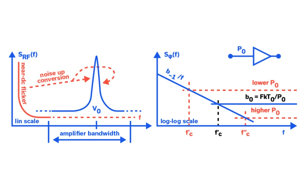
In our efforts to properly characterize the Additive Phase Modulation Noise (APM) and Additive Amplitude Modulation Noise (AAM) performance of MMIC amplifiers in our labs, Mini-Circuits is careful to consider the performance capabilities and limitations of our phase noise analyzer and test setup (see Figure 4). Both APM and AAM performance can be dependent upon the analyzer’s internal signal source carrier frequency, power level, and, importantly, the phase length from signal source output to RF input, so great care must be taken to optimize these parameters.
Frequency Modulation Fundamentals
In the 1920s, many brilliant scientists applied themselves to the study of frequency modulation (FM). One of these scientists was a communications systems theorist who worked for AT&T named John Renshaw Carson. Carson performed a comprehensive analysis of FM in his 1922 paper which yielded the Carson bandwidth rule.1 Carson was so convinced that FM was not a suitable solution to the static found in AM transmission systems that he once remarked, “Static, like the poor, will always be with us.”2
Beginning in 1923, in Columbia University’s Marcellus Hartley Research Laboratory, in the basement of Philosophy Hall, a driven genius in electronic circuitry named Edwin Howard Armstrong set out to reduce static through the use of FM. After approximately 8 years of toil, Armstrong had a brainstorm and decided to challenge the assumption that the FM transmission bandwidth had to be narrow to keep noise low. After painstakingly designing this new FM system, with as many as 100 tubes spread over several tables in the laboratory, “[Armstrong] was able to prove that wideband FM made possible a drastic reduction of noise and static.”3 Armstrong was issued patent number US1941069A, which specifically addresses noise suppression in wideband FM, on December 26, 1933, along with three additional patents for FM that same day.
The Basics of Orthogonal Frequency-Division Multiplexing (OFDM)
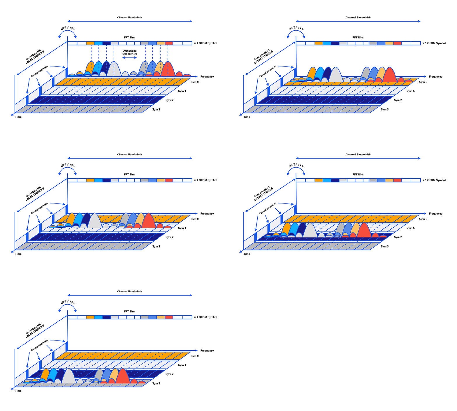
While traditional Frequency Division Multiplexing has been around for over 100 years, Orthogonal Frequency Division Multiplexing (OFDM) was first introduced by Robert W. Chang of Bell Laboratories in 1966.1,2,3,4 In OFDM, the stream of information is split between many closely-spaced, narrowband subcarriers instead of being relegated to a single wideband channel frequency.5 Single-channel modulation schemes tend to be sequential whereas, in OFDM, many bits can be sent in parallel, simultaneously, in the many subcarriers.5 So many bits can be packed onto the subcarriers simultaneously that the data rate of each subcarrier’s modulation can be much lower than that of a single-carrier architecture.
MMIC Package Customization – Footprint-Compatible Solutions for Your System
MMIC Package Customization – Footprint-Compatible Solutions for Your System Obsolescence Management and EOL Part Replacement LTB (Last Time Buy) and EOL (End of Life) are among the most unwelcome acronyms in the ranks of Procurement and Engineering. Component obsolescence saddles customers with the burden of tying cash up in inventory on their balance sheet, or […]
A Brief Overview of Phased Array Systems

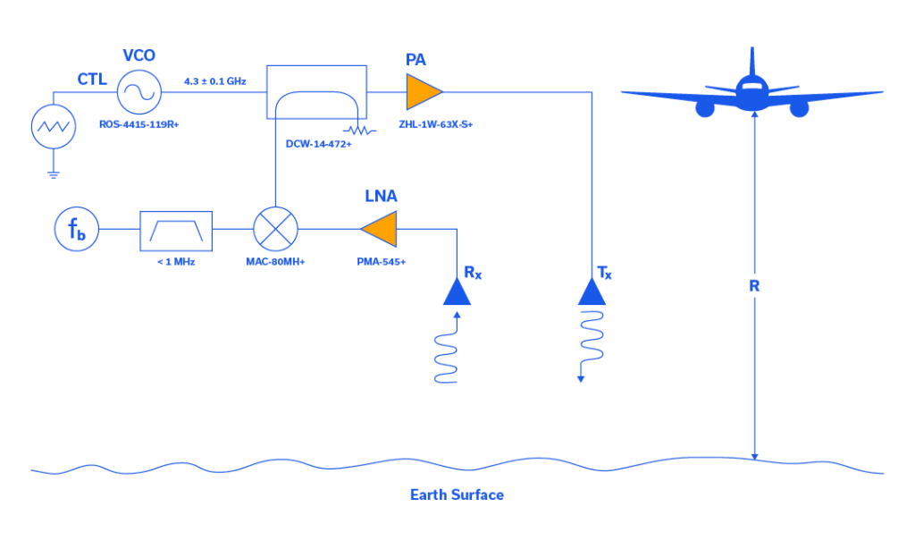
The concept of the phased array antenna system was first put into practice by German Physicist Ferdinand Braun and his assistants in the spring of 1905. In short, he and his assistants carefully controlled the excitation phase of each antenna in an array and determined that the combined effect exhibited significant directivity. In the nearly 12 decades since Braun first described the phased array antenna system, this technology has become commonplace in 4G/5G communications, electronic warfare, radar, nonlethal weaponry, and advanced imaging applications.1
This article begins with an overview of the evolution of phased array systems through history. A functional description of their basic operation in both analog and digital domains is provided, and a brief survey of common and emerging applications is given by way of example.
RF Pulse Modulation: Fundamentals, Applications & Design Techniques
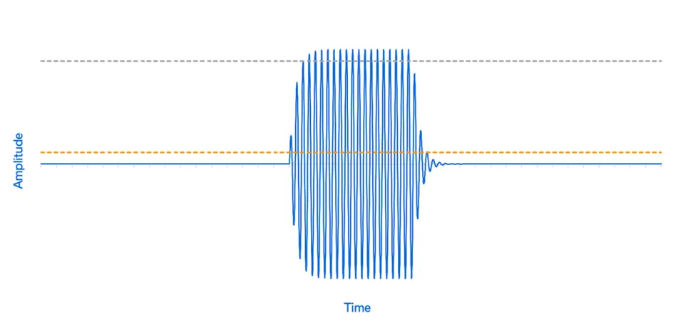
Pulse modulation has been around for over 125 years. In 1887, German physicist Heinrich Hertz built the first experimental spark-gap transmitters (electromagnetic pulse modulators), with which he proved the existence of radio waves.1 In 1888, using 455 MHz radio waves, he studied the ability of radio waves to be reflected from metallic objects and refracted by dielectric media.2 Hertz confirmed James Clerk Maxwell’s work from 1865, which was simplified by Oliver Heaviside in 1884. Hertz’s work also spawned early target detection when, in 1904, a patent for “an obstacle detector and ship navigation device,” based on the principles demonstrated by Hertz, was issued in several countries to German Engineer Christian Hülsmeyer.2 Hülsmeyer’s British patent (September 23, 1904) was for a spark-gap-type, full 600 MHz pulsed radar system that he called a telemobiloscope.
Understanding RF/Microwave Push-Pull Amplifier Design
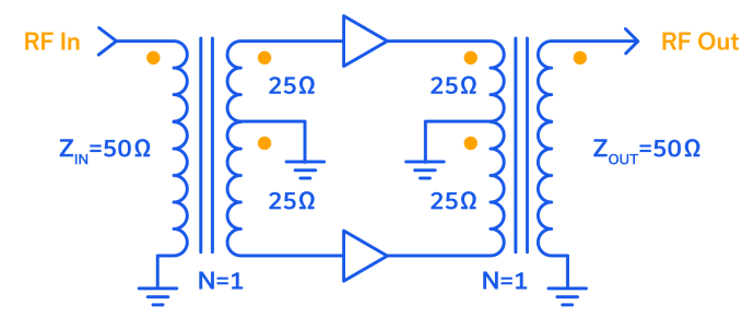
Remarkably, the concept of the push-pull connection spans three centuries. William W. Dean of the Bell Telephone Company of Missouri first described the push-pull-connected telephone transmitter in Patent No. 549,477, dated November 5, 1895.1 Next, Sir John Ambrose Fleming invented the first vacuum tube in 19042 and while Lee De Forest added the grid to Fleming’s “valve” in 1906, calling it the “audion,” it was Fritz Lowenstein in his April 24, 1912 patent application who first discovered that applying a negative bias to the grid of De Forest’s tube turned it into an audio amplifier.
Optimizing Transistor Stages for Different Operating Bandwidths
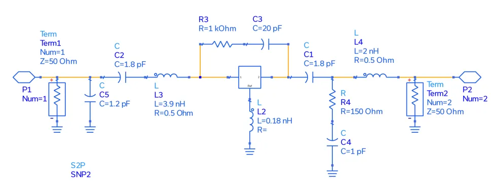
Since their invention by John Bardeen, Walter Brattain and William Shockley at Bell Labs in 1947, transistors have become a defining (if not the defining) feature of the contemporary technology landscape. Electric vehicles can have over 5 billion transistors in a given build, and today’s smartphones more than 10 billion! While their most common and familiar uses reside in the digital world, transistors are an essential element in RF circuits and systems, and while often integrated into more complex, multi-function devices, the simple transistor is still an essential tool in the designer’s toolkit.
Boost Your Knowledge: A Comprehensive Guide to RF Amplifiers – Types and Applications Explained
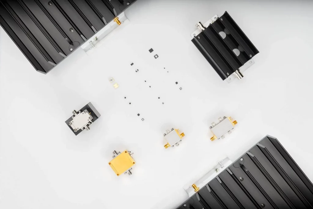
Radio Frequency (RF) amplifiers are electronic components that are used to amplify radio frequency signals. These components can be found in a wide range of applications, including wireless communication systems, television and radio broadcast systems, and medical imaging equipment. RF amplifiers are also used in test and measurement equipment, as well as in radar and satellite communication systems.
There are several different types of RF amplifiers, offering unique characteristics and uses.
RF/Microwave Balanced Amplifiers and Their Applications

A balanced amplifier is the proper term for a pair of devices operated in quadrature phase and combined to amplify a signal. Quadrature simply means that signals incident upon the devices are 90⁰ out-of-phase with one another. The term “quadrature-combined pair” (often shortened to simply “quad-combined pair”) is perhaps just as common as “balanced amplifier,” and both are as identical as “PTFE” is to “Teflon®.”
This article explains the use of quadrature hybrid splitters and combiners (also often called hybrid couplers) in balanced amplifier configurations and the advantages of combining two amplifier devices in this fashion. Two of the most common applications for the balanced amplifier (quad-combined pair) are described by way of example.


